Laser Measurement Guides Aerospace Assembly
With laser-based aircraft alignment system, wing and fuselage components for F-35 fighters find perfect fit
Patrick Waurzyniak, Senior Editor
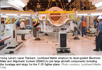
 Automating the process of mating large aircraft components can pay off great dividends for aerospace manufacturers seeking to cut costs, improve assembly quality, and speed time-to-market. With a laser-guided Electronic Mating Alignment System (EMAS), aerospace/defense giant Lockheed Martin Corp. (Bethesda, MD) employs Leica Laser Trackers from Leica Geosystems (Miamisburg, OH, and Unterentfelden, Switzerland) for fast, highly accurate mating of fuselage and wing assemblies for the F-35 Lightning II at the Joint Strike Fighter's (JSF) Fort Worth, TX, final assembly facility.
Keeping a tight rein on costs remains among the most critical goals for the JSF program, which consists of principal aerospace contractors Lockheed Martin, Northrop Grumman Corp. (Los Angeles), and BAE Systems (London) working in concert to keep costs low while maintaining aircraft quality levels and delivery schedules. At Northrop Grumman, automated assembly techniques on airframe components, including a modular, moving assembly line, are helping meet those JSF goals (see "Modular Automation for the Aerospace Industry" in the March 2006 issue of Manufacturing Engineering).
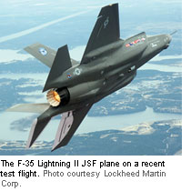
With three variants of the F-35, Lockheed Martin's use of the EMAS for measuring and mating F-35 fuselages and wings will dramatically lower overall costs by eliminating the need for multiple fixtures for the large components. The JSF program, projected to be one of the largest military procurements ever, has planned to build about 3000 of the F-35 multirole fighters. The three variants are the F-35A (Conventional Takeoff and Landing, or CTOL), the F-35B (Short Takeoff/Vertical Landing, or STOVL), and the F-35C (Carrier Variant, or CV) versions. In February, Lockheed Martin had 11 F-35 test aircraft in various stages of assembly and one plane in initial flight testing. Early production-level assembly volumes are slated for later this year, with deliveries to customers, including the US Air Force, US Navy, and US Marine Corps, the British Royal Air Force and Navy, and several allied countries, targeted for late 2009 or early 2010..
With the EMAS system, Lockheed has not only reduced costs but improved its process and quality with an inspection system that can virtually mate the components in software prior to performing the actual physical mating of aircraft components. The EMAS was installed by Lockheed's integrator, Advanced Integration Technology Inc. (AIT, Plano, TX), which recently purchased five Leica LTD800MC laser trackers for the latest versions of the system. The laser trackers from Leica Geosystems, a unit of Hexagon Metrology Inc. (North Kingstown, RI, and Sweden), were specifically designed for use in laser-guided alignment for automating and executing F-35 aircraft mating.
"The EMAS system will be capable of mating all three aircraft variations," notes Bob Ikerd, manufacturing engineer, senior staff, at Lockheed Martin's Fort Worth F-35 final assembly plant. "It does it very accurately using the laser trackers to guide the EMAS positioners into a mating configuration for each component.
"We have 13 positioners. They're basically jacks that have an X-Y-Z control move, and the actual aircraft component is monitored by the laser tracker. Each component has a certain number of targets that we've actually glued onto the aircraft structure, and these are given values based on the component or module datum.".
Lockheed Martin contracted AIT engineers to construct the assembly stations used for alignment and part mating of the F-35 modules. The EMAS system uses laser trackers and servo control positioners to mate the forward to the center fuselage, the wings to the center fuselage, and aft to the wing/center component, yielding a reduction in cost and schedule time due to its process flexibility.
The part-mating process uses a customized interface to integrate the laser tracker with the servo-driven jacks and an operator console to create the F-35 EMAS system. AIT engineers used five new laser trackers on the second and third EMAS systems. The EMAS tool can automatically point the laser tracker and acquire data from targets residing in off-the-shelf nests that have been applied to each aircraft subassembly. The laser tracker can acquire 3-D coordinate target data until the large F-35 modules are adjusted to slide into position for connectivity and assembly.
The first F-35 EMAS using Leica laser trackers successfully demonstrated its feasibility by mating the first two aircraft components that were loaded and maneuvered into nominal position before the first hole was drilled for joining the components within five days of the completion of the surrounding working platform. The EMAS cost reduction is due in part to almost no tooling and the related support expenses. A shorter assembly schedule is achieved because the process is based on highly accurate automated measurements derived from laser trackers rather than less-than-precise manual tool alignment. "We just recently mated the STOVL forward fuselage and center fuselage," Ikerd recalls. "We were able to bring the targets within a ±0.005" (0.13 mm) and most of the targets were even less than that.

"Our goal was to be able to mate it with using less than five thousandths, and we did that very quickly. The EMAS is designed to where once the laser reads the targets, it knows exactly where to position the components, and it does it within a few seconds, rather than the hours it took in the past."
Positioning large components with the EMAS takes only a few minutes, Ikerd says, while actually mating the large pieces takes longer due to drilling and fastening, some of which has to be done by hand. The system positions the fasteners that are common to that particular mate joint very accurately, he adds, and most of the fastener holes are typically a hand-drill operation. "What really restricts auto drilling is lack of space limits access to the areas that you're drilling in," Ikerd says. "The structure is rather confining."
With Lockheed building three variants on the same line, the EMAS results in substantial cost savings just in fixtures alone. "If we didn't have the EMAS system, number one, we'd have a duplication of the fixtures that would be required for each of the variants," Ikerd says. "We're using the same tooling, so we have not only a commonality in the aircraft structure, but also in the tooling."
With Lockheed building three variants on the same line, the EMAS results in substantial cost savings just in fixtures alone. "If we didn't have the EMAS system, number one, we'd have a duplication of the fixtures that would be required for each of the variants," Ikerd says. "We're using the same tooling, so we have not only a commonality in the aircraft structure, but also in the tooling."
working day, says Lockheed's John Kent. "That's a peak rate, which is a high rate," Kent states. "We're just getting started—we're not even in low-rate initial production yet. That starts this year."
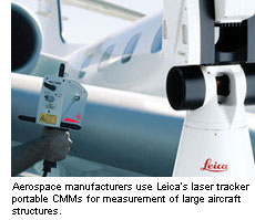
Performing a virtual mate in software enables engineers to see whether component mating will be successful even before the process is attempted on the factory floor. The direct measuring of components conforms to Lockheed Martin's digital thread foundation, starting in the design phase and distributed through every process. With the digital thread, 3-D solid models serve as master data for all processes, from flight simulation to CNC machining, fabrication, part mating, and final product assembly. Leica laser trackers are portable CMMs that deliver a fast measurement cycle for high-point density (3000 points/sec) and a measurement range reaching a full 131' (40 m) when used with a corner cube reflector. The laser trackers are used for various validation and inspection applications in the F-35 program. Before each component is shipped to the mate station, an LTD800 is used to measure reference target values and features are scanned for a virtual mate to predict shim thickness. "We know before we even load it onto the mate fixture that we're in fact going to mate without any problems," Ikerd says. "CATIA is a part of it, and Spatial Analyzer, software used with the laser trackers to view data, plus other software. It allows us to know what kind of shimming requirements we're going to have, where we have designed-in gaps between two parts. When you mate two components, you typically have to measure what your gaps are, and then the mechanics on the shop floor will cut shims that are appropriate to whatever the gap is."

Shim thicknesses usually vary more from a range of holes, rather than from hole to hole, Ikerd notes. In F-35 assembly, rather than using liquid shims, the shims used generally are solid, metal shims that are cut to fit. "It depends on the load that particular joint can be carrying. If it's a high-load area, typically it'll have to be a solid shim, a metal shim," Ikerd says. "If the adjacent structure's titanium, typically it will be titanium."
The F-35 EMAS mate concept is a bit different from systems used on aircraft programs such as the fuselage mate on BAE Systems' Tornado fighter aircraft, and also with Lockheed's earlier F-16 fighter's wing attach joint. "The Tornado's a little different," Ikerd says. "Like the F-16 wing, it had two components that just butted against one another, and you just inserted a number of bolts to hold it together. Because of weight, for the F-35 we've gone back to a more conventional type of mate joint on our components. The [F-35] airplane that's flying now we built using the EMAS system. We're working right now on our second aircraft."
High-precision assembly is critical for maintaining the F-35's stealth-signature requirements, which mandate that the outer mold line of the aircraft be as exact as possible. While early stealth efforts involved puttying and filling to help maintain a stealth signature, the F-35 is designed achieve stealth capability just through assembly accuracy.
"One of the lessons that we learned back in the mid-90s, when we were conceptualizing this airplane, was that typically a stealth airplane was very difficult for the customer to maintain in the field, and we've worked to improve that," Ikerd notes. "This aircraft will be the best-built fighter aircraft that's ever flown."
Gaging by the performance of the first F-35 test plane, the assembly quality has approached that of a production aircraft, and F-35 customers should be able to easily maintain the aircraft in the field. "Because of the technology that we've employed to build this aircraft, we're able to build it much more accurately," he says. "All the structural parts are typically NC-machined. The tooling is all NCmachined, so everything fits better. It's all driven off a 3-D solid digital model; there's essentially no variance.
"All the critical features are NCmachined, and they're set using laser trackers. The tooling is all solid-modeled on CATIA, so it's very easy, once you've taken some measurements, to determine where you're at when trouble-shooting. You have more tools to work with, where in the past, it was kind of a trial-and-error thing. If you had something that didn't fit, you didn't know where to look for the problem..
"The digital thread gives you a tool to work with, where you really know what you're doing," Ikerd states. "On an older aircraft, when you had a problem, you typically had to start measuring tools to find your problem. If you have a problem today with a tool design, you can go into CATIA to analyze the model that the tool's built from and find any discrepancy between the tooling model and the engineering model, where you weren't able to find that before.".
Using Spatial Analyzer software from New River Kinematics (Williamsburg, VA), Lockheed and Leica engineers are able to determine electronically whether the process will work as planned prior to performing the process on the floor. "Leica doesn't make a crash-avoidance tool at this point," notes Rina Molari, Leica Geosystems application engineer, "but if you have your features defined, for example, if we have BAE or Northrop Grumman send in the coordinates of their real points, in our regular software you can then marry these two data sets, whether it be from the center fuselage to the aft fuselage, or from the center fuselage to the forward. You can marry these data sets together and see how things are going to fit."
Lockheed and Leica have selected Spatial Analyzer to use with many of their applications, Molari says. "It's a software that they're using to put these pieces together," Molari explains. "If they have the data on a hole and it's off by 0.005", am I still going to be able to marry it up to another component Lockheed is making? They can do a lot of that, but it's not a crash-avoidance type of thing by any means. It's a simulation of the data of those parts coming together.
"When I think of crash-avoidance software, it's going to give you a flag, if one portion of the bulkhead comes into contact with something else that it's not supposed to, whereas this software is going to bring the datasets together, and along with the dataset comes the model. As far as I'm aware of, Spatial Analyzer doesn't have that flag that will go up and tell you you've just hit something—it's more of an analytical analysis to make sure that these pieces are going to go together.
"They are simulating the mate-up of the parts, but it's not crash avoidance," Molari says. "Their tolerances on mating are very tight. Even though we talk about numbers of 0.005", their bolt-hole tolerance oftentimes is as small as 0.003" [0.07 mm], so you've got to get these parts lined up pretty precisely. That's why they're sending their data ahead of time, such that they can perform this transformation and get an idea of 'are things going to fit?'"
Accuracies are maintained by minimizing hand-drilling. Larger structures are milled and drilled automatically, with composite wing skins machined with large autodrills. "We just drilled 6000 holes with an autodrill in a wing skin with no defects," Kent notes. Lockheed also uses machines from Dorries Scharmann Technologie (Bielefeld, Germany), builder of precision five-axis machines that drill, trim and mill to accuracies reaching the 50µm range.
"All of the upper and lower skins are auto-drilled, and the wing is built in one large component, wing tip to wing tip. It's enormous," Ikerd says, noting that the larger wing for the F-35 aircraft carrier variant has 43' wingspan, versus a standard 35' wingspan on the other two aircraft variants. "This skin's broken, but the basic wing structure is one large component when we actually mate it."


 Advanced Integration Technology > About AIT > AIT News > Laser Measurement Guides Aerospace Assembly